Smuttynose Brewing Company
Brewery digestate
75% less energyVersus tubular UF, for the same volume of water over a six-month comparison.


Separate clarified water and concentrate solids. Crossflow ultrafiltration for digestate, industrial wastewater and thickening ahead of dewatering.
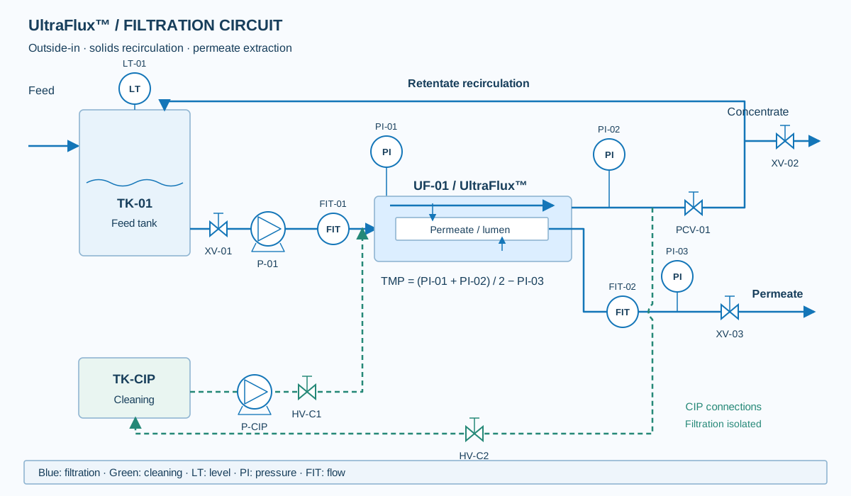
Water flows outside the membrane. Permeate passes through its pores to the inside; retained solids concentrate in the recirculation loop.
Crossflow carries deposits away and backwashing helps restore permeability. The design matches production, concentration and cleaning to your wastewater.
| Parameter | V8 | V10 |
|---|---|---|
| Active area | 10.7 m² | 35.8 m² |
| Module dimensions | Ø 8 inches × 1.5 m | Ø 10 inches × 3 m |
| Membrane material | PVDF / PESU | PVDF / PESU |
| Nominal pore size | 0.04 µm | 0.04 µm |
| Crossflow velocity | 0.5–2.0 m/s | 0.5–2.0 m/s |
| Stated maximum TMP | 207 kPa (2.07 bar) | 207 kPa (2.07 bar) |
| Operating pH | 5–12 | 5–12 |
| Operating temperature | 5–60 °C | 5–60 °C |
The limits in the table do not define a simultaneous operating point. Permeate flow, recovery and sustainable concentration are determined with the actual feed.
The range accommodates up to 150,000 mg/L TSS or up to 50,000 mg/L emulsified oil, depending on the application. These are selection references, not a guarantee of simultaneous operation or permeate flux. Viscosity, fibres, particle size, chemistry and fouling govern feasibility and are assessed for each application.
The open geometry and recirculation circuit aim to reduce pressure losses. Specific energy consumption depends on concentration, viscosity, sustainable flux and hydraulic configuration.
The anaerobic digestate comparison used 15,000–18,000 mg/L TSS and the same permeate flux per unit area. It is a test reference, not a guaranteed saving for every feed.
Versus tubular UF, for the same volume of water over a six-month comparison.
Sludge concentration before dewatering, with separation of clarified permeate.
Reduction in centrifugation time through an upstream concentration stage.
Precipitate separation in oil and gas wastewater, within a transportable platform.
Retain biomass and concentrate solids before return or dewatering.
Separate solids and colloids from production streams.
Clarify streams containing solids, colloids or pretreatment precipitates.
Concentrate the retained fraction before downstream treatment; define the permeate destination as well.
Increase feed concentration ahead of centrifuges or other equipment.
Check footprint, manifolds, pumping and controls before replacing existing modules.
Membrane area is calculated from permeate flow and sustainable flux: A = Qp/J. J must represent the actual water, design concentration, temperature and cleaning regime.
| Input | Required information |
|---|---|
| Hydraulics | Average/peak flow, operating hours and load variability. |
| Feed | TSS, total solids, total/soluble COD, oils, fibres, viscosity, pH and temperature. |
| Separation target | Permeate quality, retentate concentration and destinations for both streams. |
| Installation | Footprint, utilities, cleaning, automation and process interfaces. |
Mass-balance example with complete solids retention and equivalent densities: 5 m³/h at 2% solids → 2.5 m³/h at 4% + 2.5 m³/h permeate. This illustrates mass conservation; it does not predict flux or recovery for your wastewater.
See digestate integration guidanceUF retains solids and colloids according to their characteristics; salts, ammonium and much of the soluble organic matter can pass into the permeate. Final quality and any downstream polishing are defined from analysis.
The membrane provides the separation barrier and does not need polymer as its retention mechanism. Pretreatment, cleaning or downstream stages may require chemicals depending on the process.
There is no single flow rate for all feedwaters. Output is calculated from active area and sustainable flux validated for the wastewater. The proposal defines net production, backwashing, cleaning and availability.
A retrofit assessment checks connections, required area, pump curve, recirculation, backwashing and controls. Retrofit references do not imply universal interchangeability.
Send us your flow rate, water analysis and treatment objective.
We will review equipment selection, integration and the data needed to size your project. You can attach your water analysis or P&ID to your email.
Send project detailscomercial@neptunoes.comThe button opens your email with an enquiry template.