Inline
Water passes through the module before the next treatment stage.


Transfer gas into water with a compact porous-membrane module. For oxygenation, flotation, oxidation and cleaning in new or existing plants.
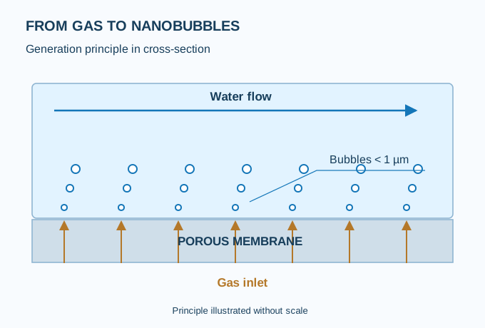
Gas crosses a porous membrane. Flowing water detaches the bubbles and carries them into the process. We select flows, gas and pressures for each application.
Nanobubbles are gas bubbles below 1 µm in diameter. At equal gas volume, reducing the diameter increases the interfacial area available for transfer.
| Parameter | Selection basis |
|---|---|
| Model identification | GENESIS™ NB-XX: numeric reference defined in the proposal. |
| Generator flow rate | Stated range: 1–100 m³/h. In a sidestream, this is not the total plant flow. |
| Process gases | Air, O₂, O₃, CO₂ and N₂; materials and configuration depend on the gas and water. |
| Energy and utilities | No motor in the core. System consumption includes pumping, gas compression or generation, and controls. |
| Gas pressure and flow | Defined for the model, backpressure and gas. The gas–liquid pressure margin is checked. |
| Water quality | Review of abrasive solids, particle size, viscosity, salinity, temperature and chemical compatibility. |
Water passes through the module before the next treatment stage.
A sidestream treats part of the flow and returns it to the process.
Take-off and return within a contact tank or reactor.
| Arrangement | Connection point | Design checks |
|---|---|---|
| Inline | Before coagulation or in a compatible treatment line. | Full flow, pressure loss and a baseline bypass. |
| Sidestream | Take-off from the reactor and a submerged return; for example in biological treatment. | Recirculation flow, oxygen transfer and minimum mixing. |
| Tank recirculation | Pre-contact, cleaning or ozone contact tank. | Working volume, contact time, suction/return positions and off-gas treatment. |
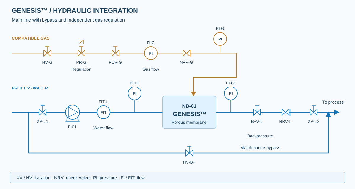
Engineering covers gas regulation and metering, inlet/outlet pressure, water flow, isolation and fault response. The operating sequence is defined in the approved equipment documentation.
Request a P&ID and model datasheetAir and oxygen for oxygenation and process trials; ozone for an engineered oxidation stage; CO₂ for carbon transfer or pH control; N₂ for specific applications.
Ozone service requires designed contact, off-gas destruction, ventilation and interlocks. Anaerobic digestion requires a specific gas selection; air or oxygen is not introduced by default.
Integration during conditioning upstream of flotation to assess interaction between bubbles, particles and flocs. The objective is to improve separation while maintaining effluent quality with optimised dosing.
Oxygen supply in reactors and sidestreams to support biomass activity. It can be assessed as additional capacity during peak loads or where oxygen transfer is limited.
Application in cleaning trials or at compatible process points to assess fouling development and permeability recovery. Particularly relevant to organic and biological deposits.
Ozone dispersion in water as part of an oxidation stage. The objective is to improve utilisation within a process designed for the target contaminant and water quality.
An evaluation pathway for studying the effects of gas transfer and substrate conditioning on anaerobic processes. Gas and dosing are selected for each reactor.
Trials upstream of thickening or dewatering to assess changes in polymer response and solid–liquid separation.
Oxygenation of irrigation water and nutrient solutions to improve oxygen availability in the root zone. Integration into tanks, recirculation systems and irrigation lines.
Oxygen supply in tanks and recirculation loops to help meet the demand of the organisms and biological treatment.
Oxygenation of water bodies to support biological balance and address oxygen deficits. Sizing considers volume, depth and organic load.
Integration into wash water and recirculation circuits to assess surface cleaning and water use. Ozone use requires a validated disinfection protocol.
Evaluation as a support measure for controlling soft deposits, biofilms and cleaning operations in compatible circuits.
Assessment of gas–particle interaction to support fines recovery, oil separation and other flotation operations in process water.
More interfacial area to support transfer into water.
Oxygenation, conditioning or cleaning to match the application.
In new or existing plants, with defined connections and utilities.
Net savings depend on the process, pumping, gas supply and maintenance. We size the complete system for your plant conditions.
Discuss my applicationThe core has no motor or moving parts. The system requires water flow and gas at design conditions, so pumping and gas supply must be included. It is not a zero-energy system.
Yes. It can be connected inline, in a sidestream or in a tank recirculation loop. Selection depends on flow, available pressure, gas and the water contact point.
Integration is proposed before coagulation or in pre-contact to assess conditioning. Flotation still requires its microbubble lifting mechanism and saturation circuit according to the DAF design.
Monitor pressures and flow rates, gas quality and transfer performance. Cleaning depends on the water and material compatibility. Shutdown and storage instructions are provided for the selected model.
Application, plant and available loop flow, water analysis, temperature, pH, pressure, gas and objective. A P&ID or sketch helps identify the connection point and required utilities.
Send us your flow rate, water analysis and treatment objective.
We will review equipment selection, integration and the data needed to size your project. You can attach your water analysis or P&ID to your email.
Send project detailscomercial@neptunoes.comThe button opens your email with an enquiry template.